Where: Platform → System page (
/system).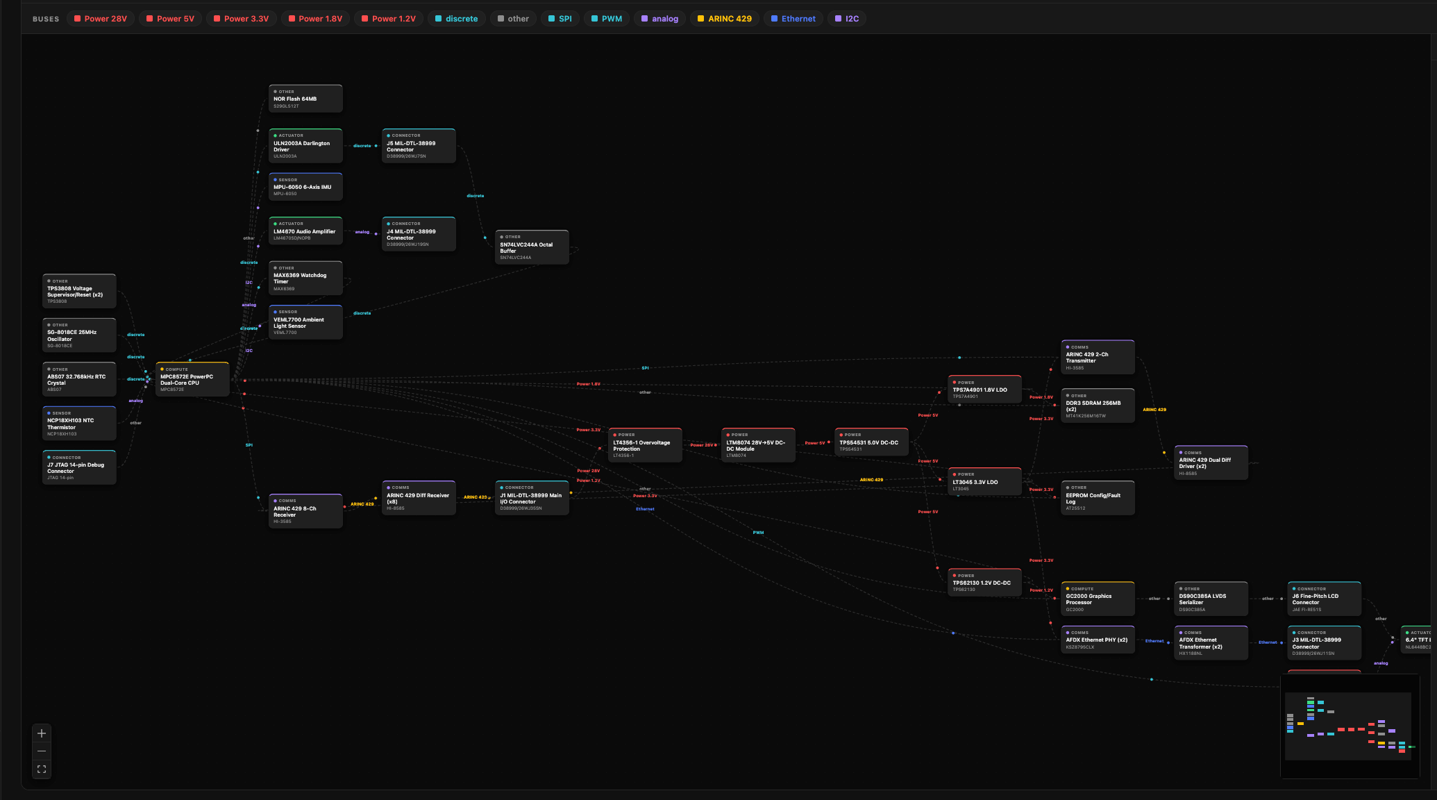
What you need
The diagram is generated from your hardware context:- BOM or schematic — at least one is required. Without either, the page points you to the Context page to upload one.
- Datasheets and requirements — optional, used to infer connections the schematic doesn’t spell out.
Generate it
Press Generate diagram. Generation runs in the background — it can take a couple of minutes — and the diagram appears when it’s ready. A model picker lets you choose which model builds it (defaults to Claude Sonnet). Hit Regenerate from the toolbar whenever your hardware changes.Read the diagram
- Blocks are components, colored by role — controller, sensor, actuator, comms, power, connector.
- Edges are connections, labeled with the bus or protocol (CAN, ARINC 429, SPI, I²C, UART, Ethernet, power…) and direction.
- Solid vs. dashed edges show confidence: a solid line is grounded in your schematic, netlist, or ICD; a dashed line is inferred from datasheets or requirements — treat it as a suggestion to verify.
Explore
- Click a block to highlight it and everything wired to it.
- Subsystem rail (right) groups blocks by function — click a subsystem to isolate it, or expand it to read its description and component list.
- Bus filter — click a protocol chip (e.g. CAN) to show only that bus.
- Data-flow toggle animates signals travelling along every edge at once, so you can watch the full data flow move through the system end to end.
- Copy Mermaid exports the diagram source for use elsewhere.
See also
- Guide → 2. Add hardware context — where the BOM, schematics, and datasheets that drive the diagram are uploaded.